
Detroit Diesel 71 Series Parts Manual

Detroit Diesel 71 Series Manual Free
Page 1 Detroit Diesel V-71 Operators Manual.; Page 2 Detroit Diesel engine.Time, money and effort have been invested in making your diesel engine a safe product. The dividend you realize from this investment is your personal safety. Need help identifying In-Line 71 series Detroit Diesel engines? Check out our online Detroit Diesel identification charts. We also supply Detroit Diesel parts with online ordering.
- 3Introduction
- 4Table of Contents
- 5Principles of Operation
- 5The Two-Cycle Principle
- 5The Two-Stroke Cycle
- 6General Description
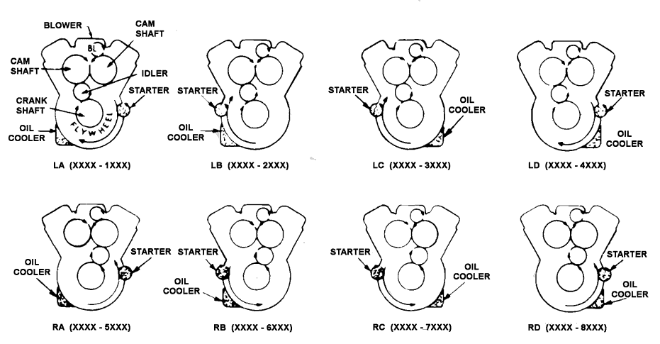
- 7Model Description, Rotation and Accessory Arrangement
- 7Views From Rear of Engine
- 8General Specifications
- 8V71 Cylinder Designation and Firing Order
- 9Engine Model and Serial Number Designation
- 9Built-In Parts Book
- 10Cross Section Views of a Typical V-71 Engine
- 11Typical Fan-to-Flywheel Unit (6V)
- 11Typical Industrial Torque Converter Unit (8V)
- 12Fuel System/Injector
- 12Remove Injector
- 12Schematic Diagram of Typical Fuel System
- 13Install Injector
- 13Fuel Pump
- 13Fuel Strainer and Fuel Filter
- 13Removing Injector From Cylinder Head
- 14Spin-On Type Fuel Filter
- 14Fuel Tank
- 14Typical Fuel Filter Mounting
- 15Air System
- 15Oil Bath Type Air Cleaners
- 15Air Intake System Through Blower and Engine
- 16Heavy-Duty Dry-Type Air Cleaner
- 16Typical Light-Duty Air Cleaner
- 16Heavy-Duty Oil Bath Air Cleaner
- 17Two-Stage Dry-Type Air Cleaner
- 17Operation
- 17Flow of Air Through Filter Element Segment
- 18Air Silencer
- 18Service
- 18Typical Dry Type Air Cleaner Mounting
- 18Silencer Assembly
- 19Air Box Drains
- 19Crankcase Ventilation
- 19Breather Pads and Retainers Installed in Cylinder Block
- 19Typical Mounting of Breather Assembly On Valve Rocker Cover
- 20Lubricating System
- 20Schematic Diagram of Typical 6V and 8V Lubricating System
- 21Oil Filters
- 21Schematic Diagram of Typical 12V Lubricating Systems
- 22Radiator and Fan Cooling
- 22Heat Exchanger Cooling
- 22Typical Full-Flow Filter Mounting
- 23Keel Cooling
- 23Cooling System View
- 24Engine Coolant
- 24Cooling System Capacity
- 24Fill/Drain Cooling System
- 25Flushing Cooling System
- 25Cooling System Cleaners
- 25Reverse-Flushing
- 25Miscellaneous Cooling System Checks
- 26Fresh/Raw Water Pump
- 26Raw Water Pump Details and Relative Location of Parts
- 28Oil Pressure/Water Temperature Gauge
- 28Ammeter and Tachometer
- 28Engine Starting Switch
- 28Stop Knob
- 29Engine Protective System
- 29Manual/Automatic Mechanical Shut-Down System
- 29Emergency Stop Knob
- 29Throttle Control
- 30Adjustment
- 30Automatic Mechanical Shut-Down System Mounting
- 31Schematic Drawing of Automatic Mechanical Shut-Down System With Overspeed Governor
- 32Automatic Electrical Shut-Down System
- 33Alarm System
- 34Alarm Bell Connected to Electrical Shut-Down System
- 35Electrical Starting System
- 35Starting Motor
- 35Starter Switch
- 35Battery-Charging Alternator
- 36Alternator Precautions
- 36Regulator
- 36Storage Battery
- 37Hydraulic Starting System (Hydrostarter)
- 37Schematic Diagram of Hydrostarter System Showing Oil Flow
- 38Initial Engine Start
- 38Remote Control System
- 38Filling
- 39Lubrication and Preventive Maintenance
- 39Purging
- 40Cold Weather Starting Aids
- 40Cold Weather Operation
- 40Marine Application
- 41Pressurized Cylinder Starting Aid
- 41Typical Fluid Starting Aid
- 42Engine Governors
- 42Governors Lubrication
- 42Quick Start Assembly
- 43Output Shaft Governors
- 44Transmissions
- 44Power Take-Off Assemblies
- 44Clutch Adjustment
- 44Power Take-Off Showing Typical 8, 11-1/2, 14 Inch Diameter Clutch Adjustment Ring
- 45Power Take-Off Assembly Showing Method of Adjusting 18 Inch Diameter Clutch
- 45Checking Power Take-Off Clutch Adjustment With Torque Wrench and Adaptor
- 46Torqmatic Marine Gear
- 46Lever Arrangement On Tandem Twin Engine Marine Gear Selector Valve
- 47Twin Disc Marine Gear
- 47Emergency Operation
- 48Snow-Nabsted Marine Gear
- 48Operating Conditions
- 48Emergency Engagement
- 49Torqmatic Converters
- 50Engine Operating Instructions
- 50Preparation for Starting Engine First Time
- 51Starting
- 52Running/Stopping
- 53Alternating Current Power Generator Set Operating Instructions
- 54Preparing Generator for Load
- 54Typical Alternating Current Generator Control Cabinets
- 55Paralleling
- 55Stopping
- 57Lubrication and Preventive Maintenance Chart
- 63Adjust Poly-V Fan Belt (16V-71)
- 63V and Poly V Belt Tension Table
- 68Snow Nabstedt Marine Gear
- 68Rockford Reduction Gear
- 70Detroit Diesel Fuel Oil Specifications
- 70Statement of Policy On Fuels and Lubricants
- 70Fuel Oil Selection Chart
- 71Detroit Diesel Lubricating Oil Specifications
- 72Coolant Requirements
- 72Water
- 72Corrosion Inhibitors
- 72Chromates/Soluble Oil
- 73Non-Chromates
- 74Coolant Inhibitor Chart
- 74Inhibitor Systems
- 74Coolant Filter Elements
Parts and service manuals for Detroit Diesel inline 71 Series engines. Diesel Parts Direct stocks new and remanufactured parts. Same day shipping available. Detroit Diesel 6-71 engine specs, bolt tightening torques, workshop manual and spec sheets by Barrington Diesel Club. In Line 71 series Detroit Diesel engine 4-71 and 6-71 Maintenance (workshop, repair) Manual. Service Information Bulletins. Service Letters. Modification Bulletins. Support Information. 176302 In Line 71 series Detroit In Line 71 series diesel engine Custom Spare Parts Catalog. Inform serial number of the engine. 176303 2-71 / 3-71. Detroit Diesel 8v-71 Dimensions and weight Dimensions approx 8v-71N length 1194 mm, 47 in width 991 mm, 39 in height 1295 mm, 51 in 8v-71T length 1270 mm, 50 in width 1016 mm, 40 in height 1346 mm, 53 in Weight approx 8v-71N 1048 kg, 2306 lb 8v-71TA 1132 kg, 2490 lb Click for Detroit Diesel 8V-71 engine manuals and specs. View and Download Detroit Diesel V 71 Series operator's manual online. V 71 Series Engine pdf manual download.